|
|
One of the most important parts of the surface mount assembly process is the application of solder paste to the printed circuit board (PCB). The aim of this process is to accurately deposit the correct amount onto each of the pads to be soldered. This is achieved by screen-printing the solder paste through a stencil or foil but also can be applied by jet printing. It is widely believed that this part of the process, if not controlled correctly, accounts for the majority of assembly defects.
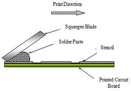
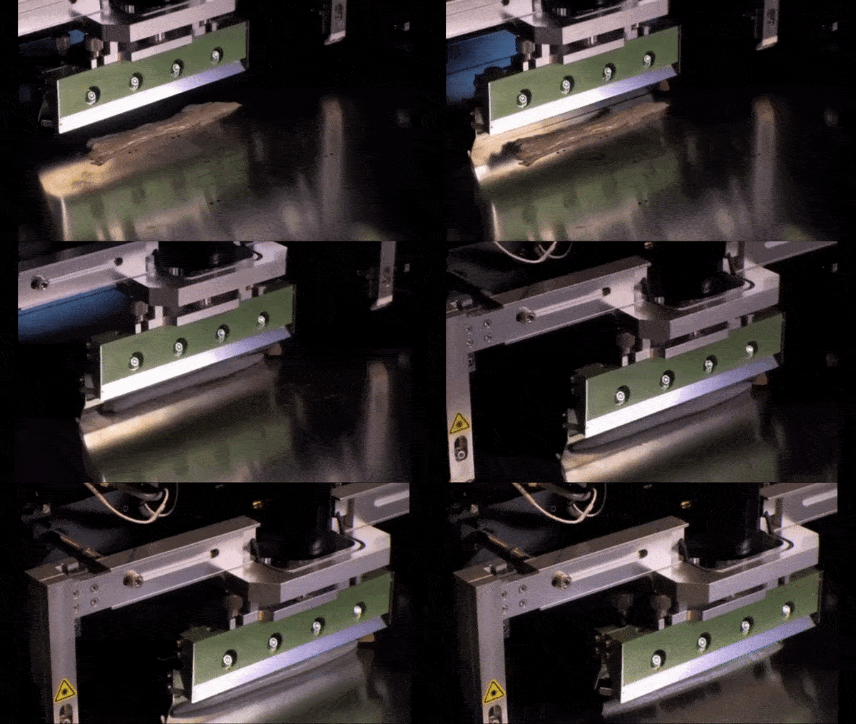
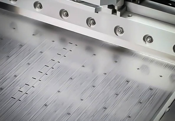
The most common method of applying solder paste to a PCB using a stencil printer is squeegee blade printing – see images below. The squeegees are the tools used to apply the necessary force required to move the solder paste across the stencil and on to the PCB. They are usually made from metal but can also be made from polyurethane.
The most common method of applying solder paste to a PCB using a stencil printer is squeegee blade printing – see images below. The squeegees are the tools used to apply the necessary force required to move the solder paste across the stencil and on to the PCB. They are usually made from metal but can also be made from polyurethane.
Solder Paste Transfer Efficiency
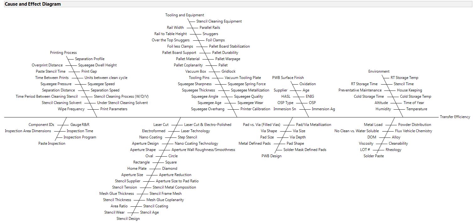
The solder paste's transfer efficiency from the stencil to the board during the printing process is determined by a number of variables. Below is a Ishikawa diagram listing many of the variables in the printing process that can affect the transfer efficiency.
Considerations
The key parameters of an effective solder paste printing process are as follows:-
|
1) Stencil Design
A stencil is a thin sheet of material (typically stainless steel) with a series of apertures (holes) cut into it which suit the PCB to be printed. The function of the solder paste stencil is to accurately deposit the correct amount of solder paste onto the surface mount pads so that the solder joint between PCB pad and component terminal are acceptable with regard to the electrical connection and mechanical strength.
2) Squeegee Speed
The speed of travel of the squeegee determines how much time is available for the solder paste to “roll” into the apertures of the stencil and onto the pads of the PCB. Typically a setting of 25mm per second is used but this is variable depending on the size of the apertures within the stencil and the solder paste used.
3) Squeegee Pressure
During the print cycle it is important to apply sufficient pressure across the entire length of the squeegee blade to ensure a clean wipe of the stencil. Too little pressure can cause “smearing” of the paste on the stencil, poor deposition, and the incomplete transfer to the PCB. Too much pressure can cause “scooping” of the paste from larger apertures, excess wear on the stencil and squeegees, and may cause “bleeding” of the paste between the stencil and PCB. A typical setting for the squeegee pressure is 500 grams of pressure per 25mm of squeegee blade.
4) Squeegee Angle
The angle of the squeegees is typically set to 60° by the holders they are fixed to. If the angle is increased it can cause ‘scooping’ of the solder paste from the stencil apertures and so less solder paste to be deposited. If the angle is reduced it can cause a residue of solder paste to be left on the stencil after the squeegee has completed a print.
5) Snap-Off / Print Gap
The 'Snap-off' or 'Print Gap' is the distance between the top side of the PCB and the bottom side of the stencil. Although there maybe some advantages of printing with a snap-off, it is generally recommended to use 'On-Contact' printing or 'Zero-Gap' as this process allows a complete gasket between the stencil and PCB. This is particularly important for printing fine-pitch components such as QFP's to reduce the risk of solder 'bridging' and solder 'bleeding'.
6) Stencil Separation Speed
This is the speed at which the PCB separates from the stencil after printing. A speed setting of up to 3mm per second should be used and is governed by the size of the apertures within the stencil. If this is too fast it will cause the solder paste to not fully release from the apertures and the formation of high edges around the deposits also known as “dog-ears” which can be seen below.
7) Stencil Cleaning
The stencil must be cleaned regularly during use which can be done either manually or automatically. Many of the automatic printing machines have a system that can be set to clean the stencil after a fixed number of prints using lint-free material applied with a cleaning chemical such as IPA. The system performs two functions, the first being the cleaning of the underside of the stencil to stop smudging, and the second is the cleaning of the apertures using vacuum to stop blockages.
8) Stencil and Squeegee condition
Both stencils and squeegees need to be carefully stored and maintained as any mechanical damage to either can lead to undesired results. Both should be checked before use and thoroughly cleaned after use, ideally using a automated cleaning system so that any solder paste residue is removed. If any damage is noticed to squeegees or stencils they should be replaced to ensure a reliable and repeatable process.
9) PCB Support
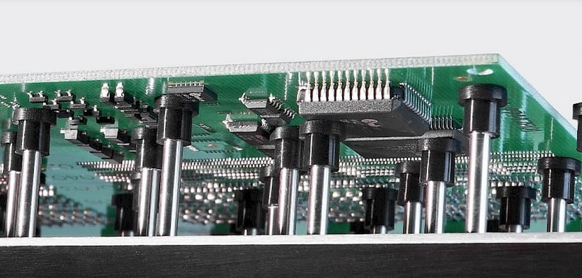
This is an important factor to ensure the PCB is held flat against the stencil during the printing process. If the PCB is not fully supported it can lead to printing defects such as a poor paste deposit and smudging. PCB supports are generally supplied with printing machines which are a fixed height and have programmable positions to ensure a consistent process. There are also adaptable PCB supports available of varying designs which mould themselves to the PCB and are useful for double sided assemblies.
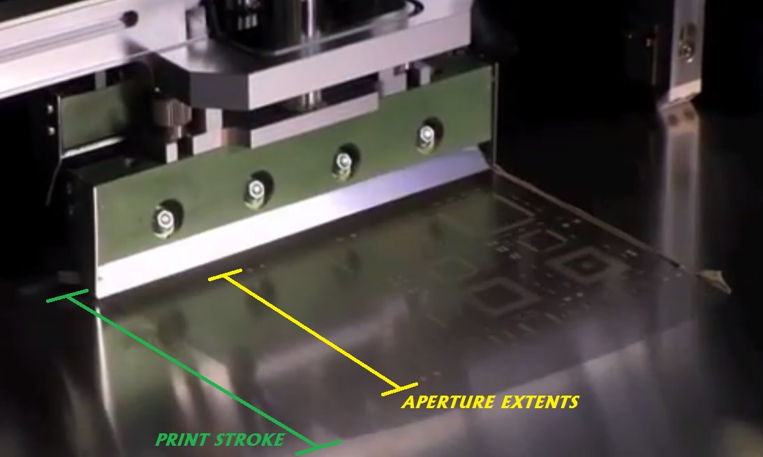
10) Print Stroke
This is the distance the squeegee travels across the stencil and is recommended to be a minimum of 20mm past the furthest aperture. The distance past the furthest aperture is important to allow enough space for the paste to roll on the return stroke as it is the rolling of the solder paste bead that generates the downward force that drives the paste into the apertures.
11) Type, Storage and Handling
Solder paste is essentially powdered solder suspended in a thick medium called flux. The flux acts as a temporary adhesive, holding the components in place until the soldering process melts the solder and forms the electrical/mechanical connection.
Solder paste is a ‘Thixotropic’ material and requires energy to be applied in the form of print head motion for it to change viscosity and flow evenly into the stencil apertures. A term often used is the ‘Rheology’ of the solder paste which describes how the solder paste forms a block when no energy is applied but changes to a more fluid material when energy is applied.
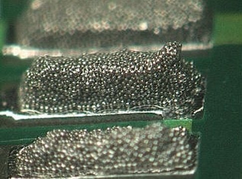
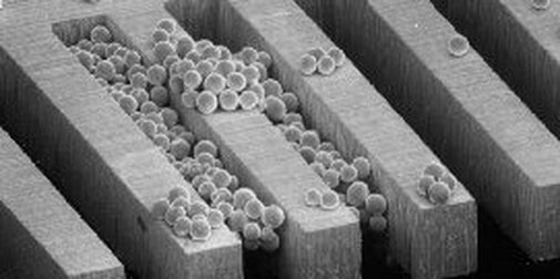
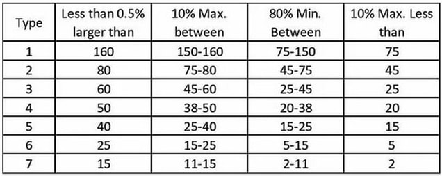
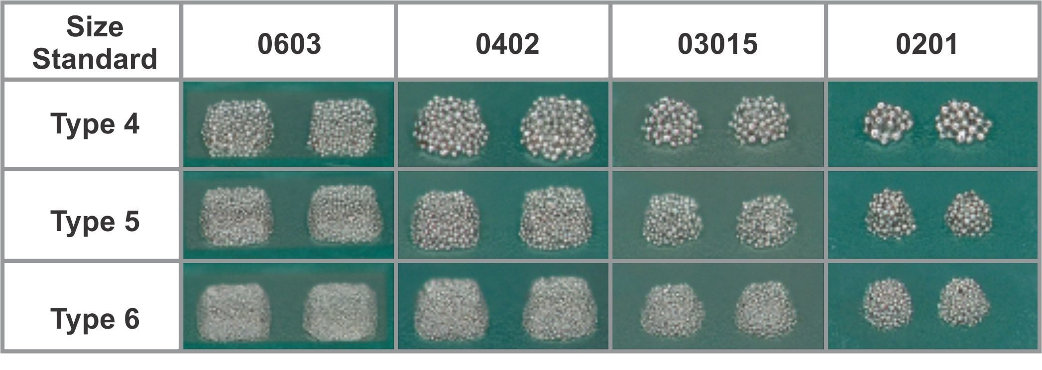
The correct type of solder paste should be selected based upon the size of the apertures within the stencil. The release from the apertures of the stencil is affected by the particle size within the selected solder paste. Below are the particle sizes available:-
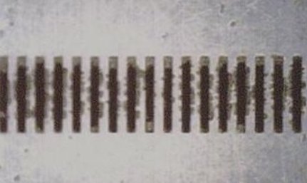
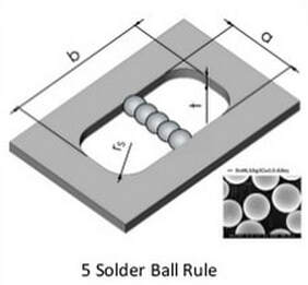
There is a ‘5 ball rule’ which says ideally a minimum of 5 solder particles should span the width of the smallest aperture.
Both Tin-Lead and Lead-Free solder paste should be refrigerated while being stored to maintain its shelf life but must be brought to room temperature for a minimum of eight hours before use to maintain quality.
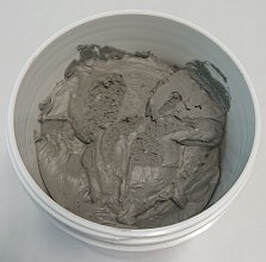
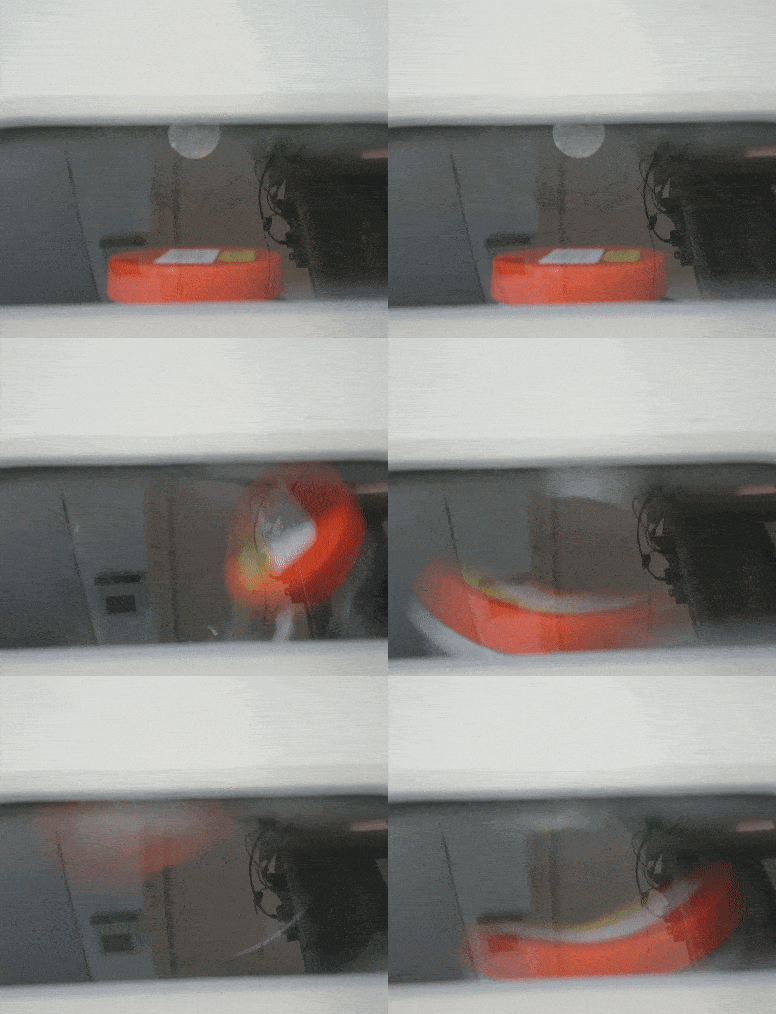
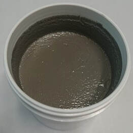
The solder paste should be mixed before use to ensure even distribution of any separated material throughout the paste. Mixing can be carried out manually or automatically using a paste conditioning machine for a duration of between three to five minutes.
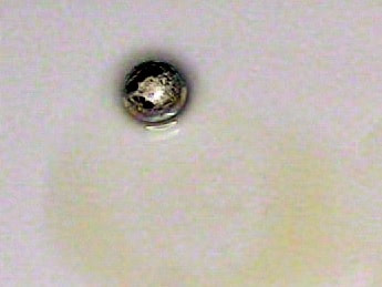
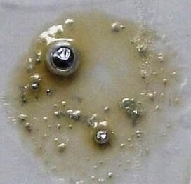
As a general rule, solder paste that has been in use for more than 8 hours should be disposed of. Solder paste which has been in use for up to 4 hrs can be stored for up to 24 hours in a sealed container at room temperature before being re-used. The working environment (ambient temperature and relative humidity) will affect the performance and so to be sure of the condition of the solder paste a simple coalescence test can be carried out. IPC J-STD-005 TM-650 2.4.43 Solder ball test as below:-
More details can be seen here regarding solder paste quality control.
Some solder paste formulations are 'Halogen-Free' to comply with environmental regulations. These solder pastes have different compositions compared to traditional solder paste that contain halogens (chlorine and bromine). If 'Halogen-Free' solder pate is intended to be used then special considerations need to be taken with respect to the different printing parameters.
Some solder paste formulations are 'Halogen-Free' to comply with environmental regulations. These solder pastes have different compositions compared to traditional solder paste that contain halogens (chlorine and bromine). If 'Halogen-Free' solder pate is intended to be used then special considerations need to be taken with respect to the different printing parameters.
12) Inspection (2D/3D)
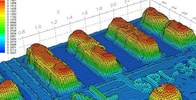
To verify the process, automatic inspection can be used to accurately check solder paste deposits. There are two types of solder paste inspection available which are 2D inspection which checks the area of the paste deposit and 3D inspection which checks the volume of the paste deposit - See 'Solder Paste Inspection Process' for more detail.
Following the solder paste print inspection, the image below shows examples of possible results:-
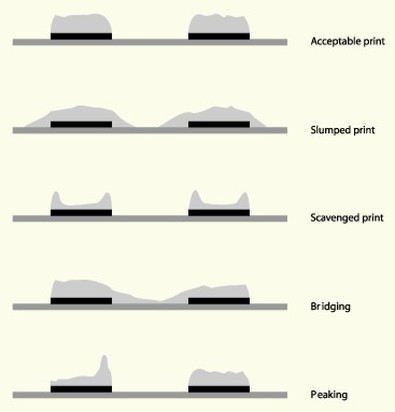
This is the target condition.
The 'Slumped print' typically occurs in a process that is run at temperatures above the recommend level.
The 'Scavenged print' result is what can be seen if the squeegee pressure is set too high and 'Scooping' occurs.
'Bridging' can be as a result of poor board support or stencil condition/cleanliness.
'Peaking' is generally noticed when the stencil separation speed is set too high.
For more detail on solder paste printing defects and possible solutions, see our 'Surface Mount Troubleshooting Guide' or videos below:-
|
|
|
Low Temperature Lead Free Solder Paste Printing
When printing low temperature lead free solder paste it is important to use the correct machine settings to achieve a consistent high quality print.
As detailed above the print speed is typically set to 25mm per second and the squeegee pressure set to 500 grams of pressure per 25mm of squeegee blade. The settings for printing low temperature lead free solder paste can be quite different and if not set correctly will cause poor print definition.
Print speeds should be much faster than conventional solder pastes ranging from 50mm per second up to 100mm per second. Squeegee pressure needs to be less than conventional solder pastes with the recommendation to apply no more pressure than is needed to get a clean stencil while printing – the setting will be nearer to 300 grams of pressure per 25mm of squeegee blade.
Another factor that needs to be considered is the amount of solder paste put on the stencil. Low temperature lead free solder paste tends to stick to the squeegee blades during use due to being lighter in weight as contains less tin. It is therefore recommended to apply more paste than with conventional solder to encourage the paste to remain on the stencil in a continuous bead.
Conclusion
The solder paste printing stage of the assembly process is vitally important. If there are errors introduced at this stage there will be “knock on” effects throughout the process. To develop the optimum solder paste printing process it is essential to consider all aspects of the process detailed above.
An Increase in Efficiency and Productivity
It’s a shocking statistic to read that within the electronics industry many surface mount operations, particularly within the sub-contract manufacturing sector, run as low as 20% efficient.
There are many reasons that contribute to this figure but it fundamentally means that only 20% of the capital investment is being utilized. Financially speaking, this will lead to a higher cost of ownership and a slower return on investment. For the customer, it can cause longer lead times for their product and therefore the business will not be as competitive in the market place.
With production efficiencies at this level there will be many knock-on effects that will have an impact on the business such as larger batch sizes, more parts in stock, more assemblies in WIP (work in progress) and slower reaction times to customer change requirements.
With all this in mind there is a strong incentive to improve efficiency while maintaining quality.
We also offer a general consultation service to discuss any particular challenge you may be facing.
If this of interest please send a message using the Contact Page
If this of interest please send a message using the Contact Page
