
So you've completed the design for a PCB assembly and need to get some samples made to test. There are an increasing number of companies around the world offering a prototype PCB assembly (PCBA) service such as PCBWay. From reading various reviews, the service offered is very good but many require an XY centroid or Component Placement List (CPL) file to be provided along with the Gerber data and Bill of Materials (BOM).
The generation of a centroid file can be a time consuming process depending on the software being used, complexity of the design and also on the available data. Some designers have the centroid file and can supply with the Gerber data and BOM but there are occasions when the centroid file isn't available or not possible to generate.
The generation of a centroid file can be a time consuming process depending on the software being used, complexity of the design and also on the available data. Some designers have the centroid file and can supply with the Gerber data and BOM but there are occasions when the centroid file isn't available or not possible to generate.
At Surface Mount Process we are offering the service to create the component placement file from Gerber data and Bill of Materials. Simply send an enquiry from the contact page.
Centroid XY files (also known as Component Placement, Pick-and-Place and XY files) are mainly used to program component placement machines but can also be used in the creation of AOI programs.
The centroid file describes the position of all of the surface mount components on the PCB. The format can vary but generally they are a semicolon/comma delimited (.csv) file and will include part number, reference designator, rotation, location in X and location in Y – an example can be seen below:-
The centroid file describes the position of all of the surface mount components on the PCB. The format can vary but generally they are a semicolon/comma delimited (.csv) file and will include part number, reference designator, rotation, location in X and location in Y – an example can be seen below:-
Example Centroid (Pick-and-Place) File
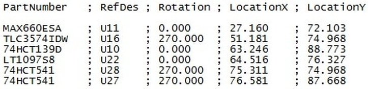
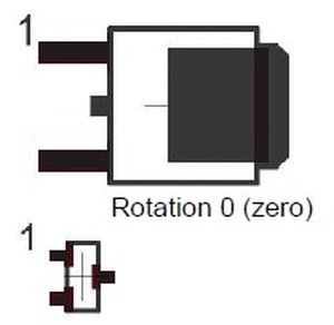
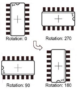
The part numbers will all be from the Bill of Materials (BOM) and will link to the PCB by the Circuit Board References (CBR). The X and Y location specify the components position relative to the board origin which is usually the center of smallest component in the lower left corner of the board and can be in inches or millimeters. The desired rotation will depend on the target machine the centroid data is required for but generally the rotation goes counter-clockwise with pin 1 as shown below:-
BGA/QFP/Duel inline chips – Pin 1 top left with rotation of zero
Three-pin devices such as SOT23 – Pin 1 top left with rotation of zero
|
|
Download the following PDF document for further details of other component type zero orientation
|
| ||
Component placement file from Gerber data and Bill of Materials
An example of the Gerber data and Bill of Materials to XY Centroid file service can be seen below:-
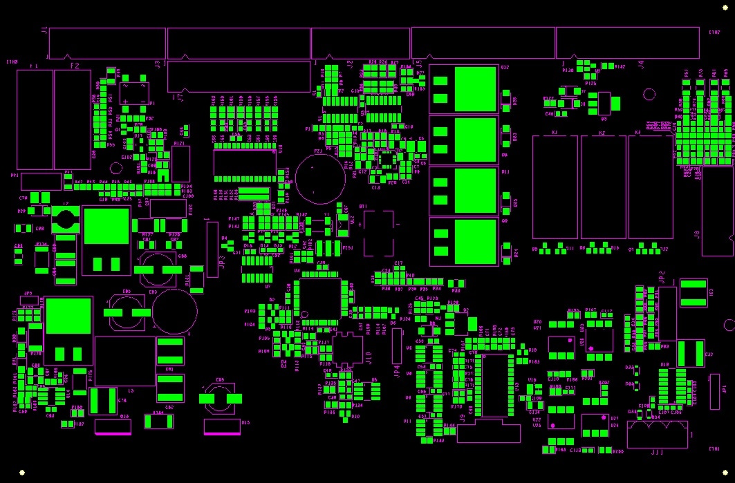
EXAMPLE GERBER DATA
|
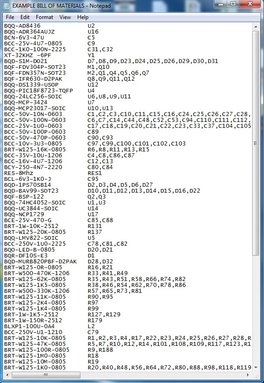
EXAMPLE BILL OF MATERIALS
| ||||
|
The data required is as follows:-
The Centroid file will contain:-
|
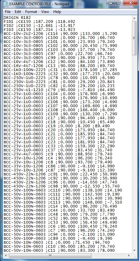
EXAMPLE CENTROID FILE
| ||
The cost for the generation of the centroid file depends on the data available and complexity of the design and so please send Gerber data and Bill of Materials to - [email protected]
An Increase in Efficiency and Productivity
It’s a shocking statistic to read that within the electronics industry many surface mount operations, particularly within the sub-contract manufacturing sector, run as low as 20% efficient.
There are many reasons that contribute to this figure but it fundamentally means that only 20% of the capital investment is being utilized. Financially speaking, this will lead to a higher cost of ownership and a slower return on investment. For the customer, it can cause longer lead times for their product and therefore the business will not be as competitive in the market place.
With production efficiencies at this level there will be many knock-on effects that will have an impact on the business such as larger batch sizes, more parts in stock, more assemblies in WIP (work in progress) and slower reaction times to customer change requirements.
With all this in mind there is a strong incentive to improve efficiency while maintaining quality.

We also offer a general consultation service to discuss any particular challenge you may be facing.
If this of interest please send a message using the Contact Page
If this of interest please send a message using the Contact Page
|
