What separation speed should be used?
The optimal separation speed in solder paste printing can vary depending on several factors, including the specific equipment, solder paste characteristics, stencil design, and PCB design. Therefore, there is no one-size-fits-all answer to the question of what separation speed to use. It typically requires some experimentation and process optimization. Here's how to determine the right separation speed:
- Consult Manufacturer Guidelines: Start by consulting the guidelines provided by the manufacturer of your solder paste, stencil, and printing equipment. These guidelines often include recommended separation speed ranges based on the product specifications.
- Solder Paste Rheology: Consider the rheological properties of the solder paste. Solder paste viscosity and tackiness can influence the separation speed. Higher viscosity pastes may require a slower separation speed, while less viscous pastes can handle a faster separation.
- Stencil Design: The design of the stencil, particularly the thickness and material, can affect the separation speed. Stencil thickness and rigidity play a role in determining the optimal separation speed. Thicker stencils may require slower separation speeds to avoid smearing, while thinner stencils may allow for faster separations.
- PCB Design: The design of the PCB, including the presence of fine-pitch components, component density, and solder pad sizes, can impact the separation speed. More complex PCBs with fine-pitch components may require more precise and slower separation speeds.
- Equipment Capabilities: The capabilities of your solder paste printing equipment, such as the speed at which it can lift the stencil, will also influence the optimal separation speed. High-quality and modern equipment may offer greater control over this parameter.
- Experimental Testing: Perform a series of test prints using different separation speeds to assess the quality of solder paste deposits. Inspect the resulting solder deposits for defects like smearing, bridging, or insufficient volume. Continuously adjust the separation speed until you achieve the desired solder paste quality.
- Real-Time Monitoring and Control: Some advanced solder paste printing equipment is equipped with real-time monitoring and control systems that can adjust the separation speed on the fly. This can help maintain optimal conditions during the printing process.
- Document the Optimal Settings: Once you have determined the optimal separation speed for your specific application, document these settings and ensure that they are used consistently in the manufacturing process.
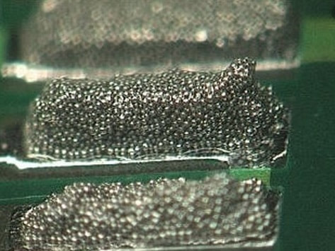
Effect on Solder Paste Deposits:
- Slow Separation Speed: A slow separation speed (lifting the stencil slowly) has little effect on the quality and repeatability of the solder paste print but will slow down the process. This can be a problem if high throughput is needed.
- Fast Separation Speed: A fast separation speed (lifting the stencil quickly) can cause inconsistent printing results such as insufficient or excessive solder paste deposition. It can also cause 'shape' errors due to the edges of the solder paste deposit being raised, often referred to as 'dog-ears', 'tailing' or 'peaking'.
Remember that process optimization is an ongoing effort. Changes in solder paste formulations, stencil wear, or variations in PCB designs may require periodic reevaluation and adjustment of the separation speed to maintain high-quality solder paste printing.
