|
|
There are many different types of component placement machine (also known as pick and place machines) available on the market with the same aim of placing surface mount components as accurately and quickly as possible.
As the variety of available components has increased, so has the capability of these machines and so it can be a daunting prospect having to decide on a particular manufacturer. The type of business will have a large bearing on the decision as some machines are designed specifically for speed whereas others are more focused on flexibility.
The machines designed for speed are generally referred to as ‘chip shooters’ and can achieve component placement rates of up to 100,000 cph (components per hour). The flexible placers can handle components ranging from 01005 to 150mm connectors and have the ability to inspect/place micro BGA (Ball-Grid-Array) and PoP (Package-on-Package) devices.
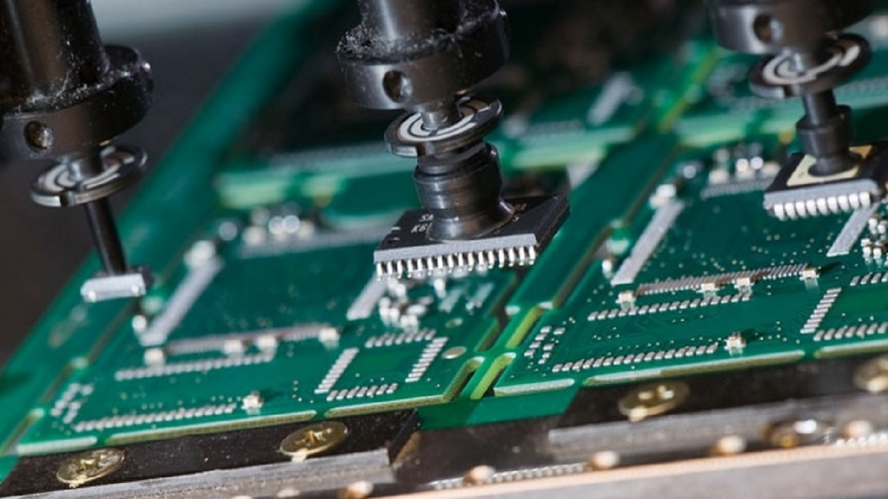
The general concept is that PCB’s printed with solder paste are fed into the placement machine where they are transported by way of conveyor to the placement area and clamped. The machine’s vision system then confirms the PCB’s fixed position using fiducial marks and starts the component placement program.
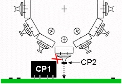
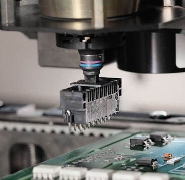
The component placement process consists of picking each component in turn from a feeder using a nozzle and transporting to the programmed position.
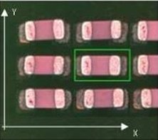
Each type of placement machine has its own format for programs but they all contain the same information including - part numbers, circuit board reference, rotation, package information and X/Y position.
Once complete the assembly is unclamped and transported by conveyor to the next machine in the line.
Key aspects of the component placement process
|
In order to achieve a reliable and repeatable process the following points need to be considered:-
|
Type of Data Available
Generally when PCB’s are designed the software used has the ability to output various types of data. The most common is ‘Gerber’ data which is a standard electronics industry file format and is used to communicate design information to PCB manufacturers - gerber data can be viewed online here. This includes data such as tracking, solder resist, silk screen and drill information and is necessary for the bare PCB to be manufactured.
It is possible to generate placement programs (also known as a component placement list (CPL file) or XY centroid data) from Gerber data but this can be very time consuming and there is a high chance of errors occurring.
Surface Mount Process offers a service to generate a centroid file here.
It is possible to generate placement programs (also known as a component placement list (CPL file) or XY centroid data) from Gerber data but this can be very time consuming and there is a high chance of errors occurring.
Surface Mount Process offers a service to generate a centroid file here.
The best type of data for generating placement programs is known as ‘CAD’ data which is a complete description of the design and is available in many formats. CAD data contains all the same information that is within Gerber data along with further information such as the component centroids, references and rotation. For details on how to obtain CAD data from various PCB design packages please refer to ‘CAD Extraction from PCB design Software’.
PCB Panel Design
The design of the PCB and how the PCB is panelized will have an effect on the component placement process. The following is a list of considerations:-
- Panel Size – All machines will have a specified maximum and minimum board size they can process.
- Handling Strips – It is quite common for PCB’s to be designed with components positioned close to the edge and so because of the PCB handling mechanism within the various machines it is important to panelize the PCB.
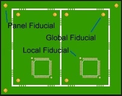
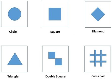
- Fiducial Marks - Fiducial marks are simply shapes within the track layer of the PCB that are positioned where they cannot be confused with other aspects of the board design. – Examples can be seen below:-
Fiducial marks are used by the placement machines vision system to ensure all components are accurately positioned. It is recommended to use the fiducials furthest apart when aligning the PCB in the machine to achieve the greatest accuracy and also to use three fiducials to make it possible to determine if the PCB has been loaded correctly.
- Component size and position – Highly populated designs may have small components positioned close to larger components which needs to be taken into account when generating the placement program. All smaller components need to be placed before larger parts to ensure they do not get disturbed - this is normally taken into account by the placement program optimizing software.
Nozzles
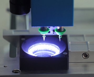
Due to the increasing number of surface mount components available on the market there are also many different types of nozzle available. Most nozzles use vacuum to hold the component securely between the picking and placement steps but this does rely on the component having a flat top surface. The alternative is a gripper nozzle which grips the component sides and uses the vacuum to actuate the mechanism.
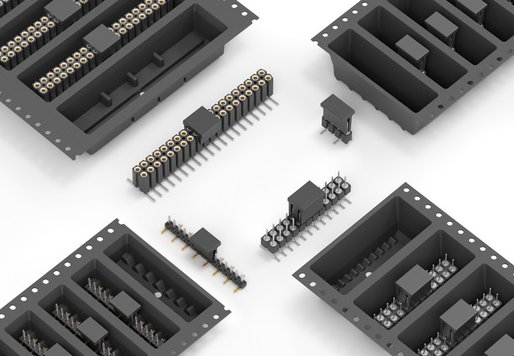
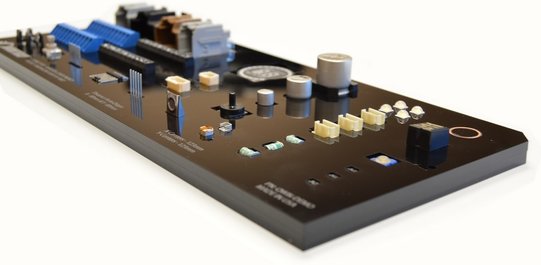
Certain components such as connectors that do not have a flat top surface can be specified to be bought from the supplier with a pad/insert that will allow vacuum pick and place.
Certain components such as connectors that do not have a flat top surface can be specified to be bought from the supplier with a pad/insert that will allow vacuum pick and place.
It is very important that the correct nozzle be selected for each different part to be placed to ensure accurate and consistent placement – a selection can be seen below:-
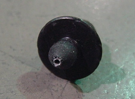
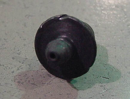
It is important to regularly check the nozzles for problems such as solder paste contamination as can be seen below. This can cause components to stick to the nozzles during the pick and place process and lead to defects such as missing or misplaced parts.
Vision System
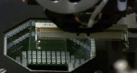
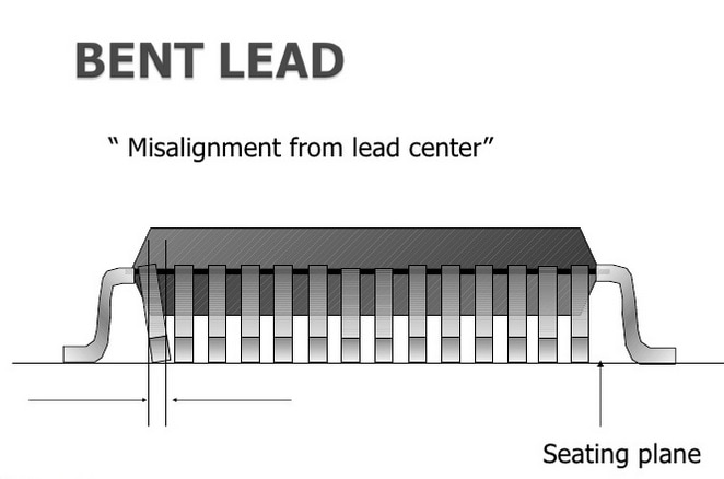
Every component that is picked is analysed by the machines vision system before placement to ensure that all the programmed part dimensions match and also to check for any damage such as bent leads. It is important to program each component with the correct tolerance parameters to allow the machine to determine if an incorrect part has been loaded and also not to reject acceptable parts.
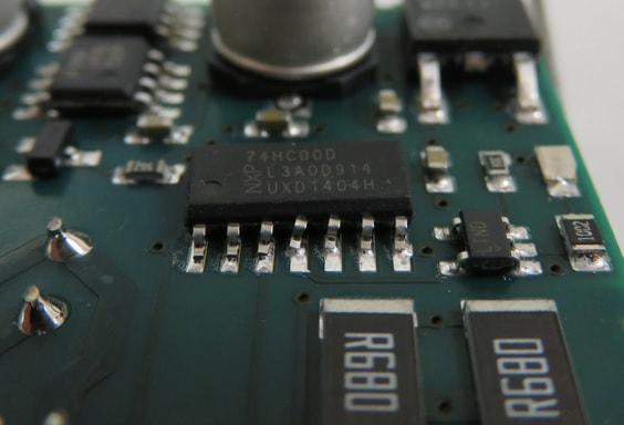
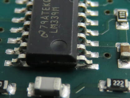
The following are two defects that the vision system is designed to detect:-
|
|
|
PCB Support
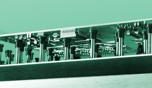
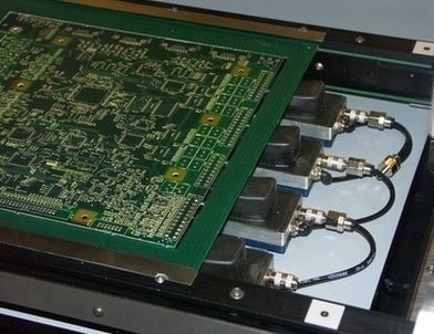
Most PCB’s are made from fairly rigid 1.6mm FR4 material but when thinner material is used or if there are slots routed the PCB can be a challenge to support. This can lead to inconsistent results during the component placement process as there will always be a certain amount of placement pressure - if the PCB is not fully supported it will deflect. Setting up the support can be time consuming and so there are a number of adaptable systems available that can be seen here. Not only are the adaptable support systems quick to setup they also take into account if double sided assemblies are to be built with components already mounted to the underside. Two of the most common solutions can be seen below which mold themselves around the already placed components.
How Components are Supplied
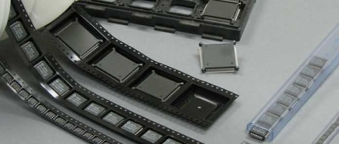
Surface mount components are supplied in a number of ways, the most common being tape/reel, tubes and trays. All machine manufacturers have feeders for this type of packaging but problems can arise when only small quantities of components are needed for small batches of assemblies. In this case components quite often are supplied in ways that cannot be directly loaded to the machine and so either get sent away to be put into packaging mentioned above or hand placed – both of which are not ideal as can be costly, time consuming and a quality concern.
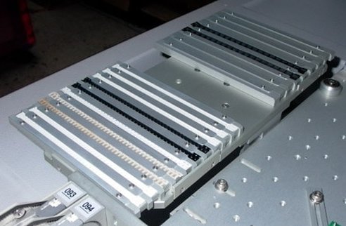
In the case of components supplied in tape, if only small quantities are required there are many ‘short-tape’ feeding methods available that can loaded as a tray, see below:-
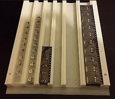
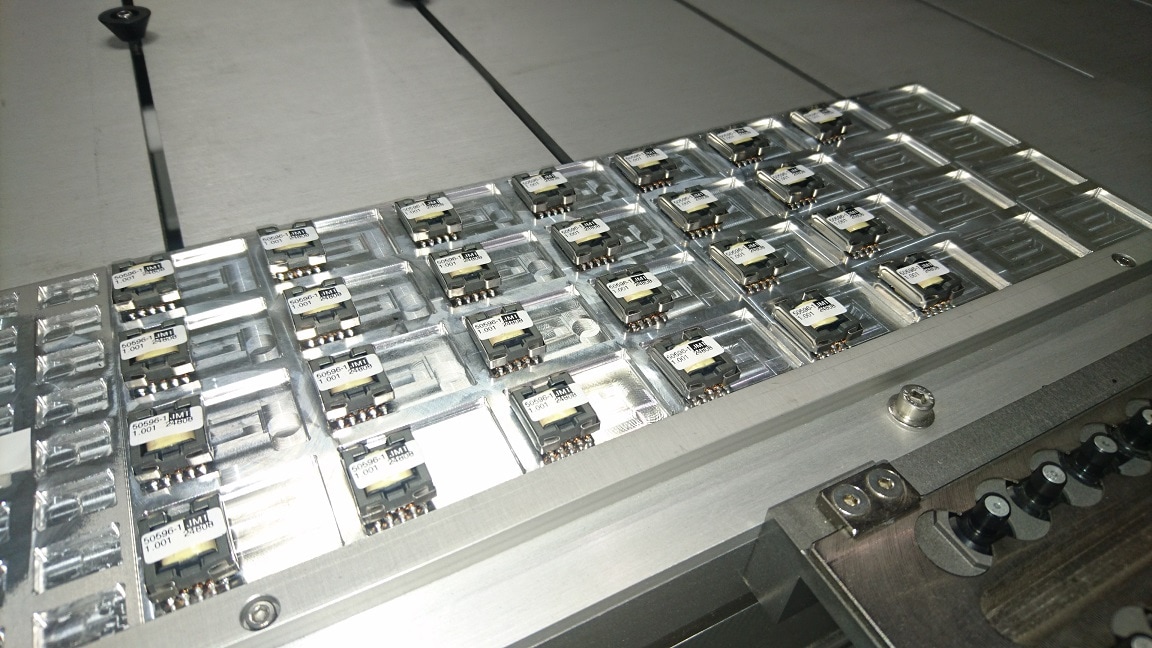
For larger components or if components are supplied loose there are companies that can manufacture custom feeding trays such as the ones seen below.
Stock Control and Component Attrition
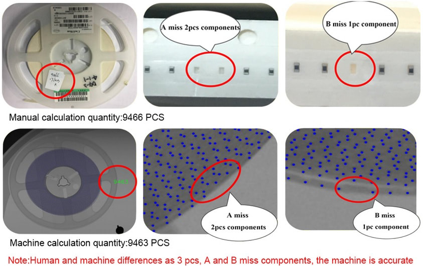
Stock control and component attrition management are essential aspects of efficient and cost-effective surface mount assembly in electronics manufacturing. Proper stock control ensures that you have the right components and materials available when needed, while attrition management focuses on reducing losses and damage during the assembly process. Strategies to address this concern include use of ERP software to include attrition rates for each part number to account for losses during kitting and assembly process. X-ray component counting machines are also available that allow reels, tubes and trays of components to be accurately/quickly counted when issued to a kit or returned to stores.
Conclusion
The component placement process is a relatively straight forward concept but as can be seen above there are a number of aspects that need to be controlled to ensure repeatable results. For companies building high volumes of a small number of different assemblies this part of the surface mount process is generally the least concern but for companies building high mix/low volume such as CEM’s it can prove to be a challenge to maintain consistency.
An Increase in Efficiency and Productivity
It’s a shocking statistic to read that within the electronics industry many surface mount operations, particularly within the sub-contract manufacturing sector, run as low as 20% efficient.
There are many reasons that contribute to this figure but it fundamentally means that only 20% of the capital investment is being utilized. Financially speaking, this will lead to a higher cost of ownership and a slower return on investment. For the customer, it can cause longer lead times for their product and therefore the business will not be as competitive in the market place.
With production efficiencies at this level there will be many knock-on effects that will have an impact on the business such as larger batch sizes, more parts in stock, more assemblies in WIP (work in progress) and slower reaction times to customer change requirements.
With all this in mind there is a strong incentive to improve efficiency while maintaining quality.
|
