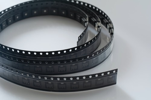
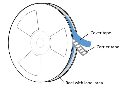
Tape and reel packaging is the best way to handle, process, store, and transport electronic components. It provides protection and makes precision surface-mounting of components easy. The tape and reel packaging process uses individual pockets on the carrier tape. Each pocket houses an electronic component that is then covered with heat or pressure seal cover tape. The tape containing sealed pockets of parts is then wrapped around a reel. Manufacturers must follow tape and reel packaging standards. This ensures that there are no problems during the automated surface mounting of components.
Electronics Industries Alliance (EIA)
The Electronics Industries Alliance began in 1924 as the Radio Manufacturing Association. The company was fundamental in establishing standards for electronic components and consumer products.
The JEDEC Solid State Technology Association of EIA was formed in 1958. The JEDEC deals with semiconductor standards and sets the global standards for the microelectronics industry.
The JEDEC Solid State Technology Association of EIA was formed in 1958. The JEDEC deals with semiconductor standards and sets the global standards for the microelectronics industry.
EIA-481 Tape and Reel Packaging Standards
EIA-481 tape and reel standards provide manufacturers and purchasers with guidelines, which eliminates misunderstandings and improves product quality. The standards are recommendations only. They do not stop the manufacture or sale of non-compliant products. Below are the standards for the tape and reel process of surface-mount components. The recommendations provide the dimensions and tolerances necessary. These allow the automatic handling of components in surface-mounting applications.
| eia-481-2003.pdf | |
| File Size: | 648 kb |
| File Type: | |
Standards include figures and tables that the component manufacturer must follow. This applies to carrier tapes, reels, cover tapes, and taped components. All procurement documents and quotes must contain the following:
Weight is a vital component. Heavy reels may not work on all feeders. Manufacturing facilities must know the weight of a reel on the feeder. They must follow corporate or regulatory weight limits applicable to lifting by employees. Many conditions may result in problems. These may cause the carrier tapes or tape-feeding systems to malfunction. Procurement documents and quotes must reference every potential problem.
- Reference to the standard by title and number
- Tape quality requirements, including the maximum number of missing components
- Container and reel marking requirements and reel diameter
- Shipping and storage conditions and storage time
- Weight of reel components
Weight is a vital component. Heavy reels may not work on all feeders. Manufacturing facilities must know the weight of a reel on the feeder. They must follow corporate or regulatory weight limits applicable to lifting by employees. Many conditions may result in problems. These may cause the carrier tapes or tape-feeding systems to malfunction. Procurement documents and quotes must reference every potential problem.
Component Tape Standards
The carrier tape must meet specific standards for automatic tape and reel dispensing. The sprocket holes must not have any cover tape over them. The cover tape cannot go beyond the edge of the carrier tape. The tape cannot stick to adjacent layers when wound around the carrier wheel.
After removal of the top cover tape, components may not be allowed to fall out of the carrier tape. They must remain in position during the automatic application process. A tape may never contain spots where consecutive parts are missing from the reel.
The process, packaging, and materials cannot impact the components. This includes their markings and their electrical and mechanical characteristics. Additional guidelines exist for further reference, including:
The tapes must be able to withstand storage. They cannot suffer contaminants getting onto the termination. Tapes may not emit vapors that cause problems with soldering or cause the deterioration of components.
After removal of the top cover tape, components may not be allowed to fall out of the carrier tape. They must remain in position during the automatic application process. A tape may never contain spots where consecutive parts are missing from the reel.
The process, packaging, and materials cannot impact the components. This includes their markings and their electrical and mechanical characteristics. Additional guidelines exist for further reference, including:
- EIA-383—Preparation for the Delivery of Electrical and Electronic Components
- EIA-541—Packaging Material Standards for ESD Sensitive Items
- EIA-583—Packaging Material Standards for Moisture Sensitive Items
- EIA-624—Product Package Bar Code Label Standard for Non-Retail Applications
The tapes must be able to withstand storage. They cannot suffer contaminants getting onto the termination. Tapes may not emit vapors that cause problems with soldering or cause the deterioration of components.
Cover Tape Standards
The cover tape on the reel must meet specifications for peel strength and width. It must pull in the opposite direction of the carrier tape at a 165- to 180-degree angle. The cover tape must pull off at a velocity of 300mm, resulting in a separation rate of 150mm per minute.
The cover tape must fit securely on the reel. It cannot detach during storage. The punched carrier must not incur breakdown, delamination, or lose strength in storage.
There must be no delamination when unreeling. This includes unreeling by hand or in an automatic tape and reel machine.
There may be situations requiring the removal of components from the cavity. Removal is accomplished by making an incision on the bottom cover tape or near the cavity depth midpoint. The incision cannot affect the function of the packaging.
Each reel must include barcode labeling. The proper placement is on the reel's side, opposite the round sprocket holes. The reels must also display the appropriate recycling symbol.
More information on requirements is in EIA-556 and EIA-624.
Orientation Rules
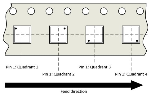
There are orientation rules for multi-connection components. Leaded, bottom-only terminations must face the bottom of the carrier cavity. The following descriptions apply whether the termination faces up or down within the cavity:
- A termination is the connection between the component and the board
- The orienting feature is what identifies a unique orientation on the component
- A component is square if the outer extents have edges of equal length
- The tape pocket quadrant describes the tape orientation of components
- Use the rules in order when viewing the component orientation flow chart in figure 2 on page 14 of the EIA guide
Tape and Reel Packaging for Semiconductor Devices
Semiconductor packaging follows the same EIA-481 standards as other products. Three methods are available. The high-volume process handles families of devices. It includes advanced vision inspection technology. This provides higher yields and less downtime.
With the rotary process, a rotary turret picks up the device. It then moves the device to the next station. In the single-arm process, a vacuum head on a swing arm picks up the semiconductor. It then puts the device into the carrier tape.
When using tape and reel, you select a carrier tape that meets your needs. Tape widths are available from 4 mm to 200 mm. Spacing between components is available from 2 mm and up. Standard reel diameters include 7” for small components. You may select 13” for larger items. The carrier tape is usually paper or plastic. For small components, plastic is recommended. Polystyrene and polycarbonate tapes are popular. They are higher in cost but hold their shape well. Semiconductors need protection from electrostatic damage. You can select from three options:
Carrier tape protects the semiconductors. It is available in heat-activated or pressure-activated.
Heat-activated is most common and least expensive. Pressure-sensitive tape peels more uniformly, increasing production speed.
With the rotary process, a rotary turret picks up the device. It then moves the device to the next station. In the single-arm process, a vacuum head on a swing arm picks up the semiconductor. It then puts the device into the carrier tape.
When using tape and reel, you select a carrier tape that meets your needs. Tape widths are available from 4 mm to 200 mm. Spacing between components is available from 2 mm and up. Standard reel diameters include 7” for small components. You may select 13” for larger items. The carrier tape is usually paper or plastic. For small components, plastic is recommended. Polystyrene and polycarbonate tapes are popular. They are higher in cost but hold their shape well. Semiconductors need protection from electrostatic damage. You can select from three options:
- Conductive tape lets electrical current pass through
- Dissipative tape stops electrostatic discharge
- Non-conductive tape is insulating and prevents electricity from passing through
Carrier tape protects the semiconductors. It is available in heat-activated or pressure-activated.
Heat-activated is most common and least expensive. Pressure-sensitive tape peels more uniformly, increasing production speed.
|
Return to home page
|


