|
|
Type 3 solder paste is generally considered to be the industry standard that will work for most printing applications. The use of Type 4 is really only needed for particularly fine-feature printing, where the Type 4 will produce better release and a more consistent volume deposit.
The point at which Type 4 solder paste should be considered over Type 3 solder paste in printing applications is generally in the range of a 9-mil stencil aperture width for most pastes, although other variables such as paste chemistry, stencil thickness and other printer parameters can have an impact. This means that Type 3 paste will generally work well down to an aperture with an opening of 9 mils or greater. For apertures that are narrower than 9 mils in width, the user is best off using Type 4 paste to assure consistent release from the stencil.
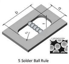
The rule of thumb that is appropriate in this case is called the "Five-Ball Rule." This rule says that you need to be able to fit five of the largest powder particles across the narrowest aperture in order to achieve good stencil release. Also discussed within the article A GUIDE TO EFFECTIVE STENCIL DESIGN
Since Type 3 paste has a specification of 45 - 25 microns (roughly 1.0 - 1.8 mils), you can fit 5 of the largest powder particles across a 9-mil stencil aperture (5 particles x 1.8 mils per particle = 9 mils). If the aperture were any smaller than 9 mils, the Type 3 paste would fail the Five-Ball Rule and the user should consider Type 4 powder instead.
The point at which Type 4 solder paste should be considered over Type 3 solder paste in printing applications is generally in the range of a 9-mil stencil aperture width for most pastes, although other variables such as paste chemistry, stencil thickness and other printer parameters can have an impact. This means that Type 3 paste will generally work well down to an aperture with an opening of 9 mils or greater. For apertures that are narrower than 9 mils in width, the user is best off using Type 4 paste to assure consistent release from the stencil.
The rule of thumb that is appropriate in this case is called the "Five-Ball Rule." This rule says that you need to be able to fit five of the largest powder particles across the narrowest aperture in order to achieve good stencil release. Also discussed within the article A GUIDE TO EFFECTIVE STENCIL DESIGN
Since Type 3 paste has a specification of 45 - 25 microns (roughly 1.0 - 1.8 mils), you can fit 5 of the largest powder particles across a 9-mil stencil aperture (5 particles x 1.8 mils per particle = 9 mils). If the aperture were any smaller than 9 mils, the Type 3 paste would fail the Five-Ball Rule and the user should consider Type 4 powder instead.
|
Particle size in microns Particle type
75-45 2 45-25 3 38-20 4 25-15 5 15-5 6 |
|
