What is the 'floor life' for the different moisture sensitivity levels (MSL)? |
|
What is the 'floor life' for the different moisture sensitivity levels (MSL)?
|
The Moisture Sensitivity Level (MSL) indicates the floor life of the component, its storage conditions, and handling precautions after the original container has been opened. The permissible time (from opening the moisture barrier bag until the final soldering process) that a component can remain outside the moisture barrier bag is a measure of the sensitivity of the component to ambient humidity.
|

|
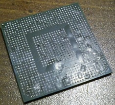
In many cases, moisture absorption leads to moisture concentrations in the component that are high enough to damage the package during the reflow process. The expansion of trapped moisture can result in interfacial separation, known as delamination, of the mold compound from the die or lead-frame, wire bond damage, die damage, and internal cracks. In the most severe cases, the component will bulge and pop, which is known as the 'popcorn' effect. See 'Surface Mount Troubleshooting Guide' for other defects.
|
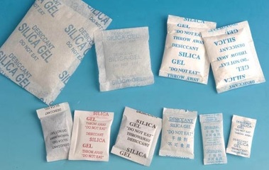
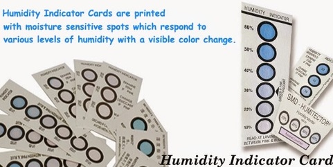
Therefore, it is necessary to dry moisture-sensitive components, seal them in a moisture barrier antistatic bag (with a desiccant pack and a moisture indicator card), which is then vacuum sealed according to J-STD-033 - see link below. Only remove the moisture-sensitive components immediately prior to assembly onto the PCB.
|
|
| j-std-033b01.pdf |
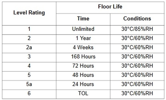
The MSL is expressed as a numerical value, typically ranging from MSL 1 to MSL 6, with higher numbers indicating higher sensitivity to moisture. Here's what each MSL level signifies:
- MSL 1: Components in this category have the lowest sensitivity to moisture and can typically be exposed to ambient air without special precautions. They have a long shelf life and are considered moisture-insensitive.
- MSL 2: Components in this category have low to moderate moisture sensitivity. They can be exposed to ambient air but are recommended to be reflow soldered within a specified time frame, usually indicated as the "floor life" or "floor time." After this time elapses, the components should be baked to remove absorbed moisture before soldering.
- MSL 3: Components at this level are moderately sensitive to moisture and have a limited floor life. Exposure to ambient air should be minimized, and they typically require more stringent handling and storage procedures. Components may need to be baked before soldering if they have exceeded their floor life.
- MSL 4: Components with an MSL of 4 are considered fairly sensitive to moisture. They have a shorter floor life and require careful handling, storage in moisture-barrier bags (MBBs) with desiccants, and possibly pre-baking before soldering.
- MSL 5: Components rated as MSL 5 are highly sensitive to moisture and have a very short floor life. They require stringent handling, storage in MBBs with desiccants, and baking before soldering in many cases.
- MSL 6: Components in this category are extremely sensitive to moisture and have the shortest floor life. They must be stored in a dry environment at all times, typically in a dry cabinet or dry box. Baking before soldering is often required.
|
|
|
|
|
Learn the difference between adsorbent and absorbent from Steel Camel HERE
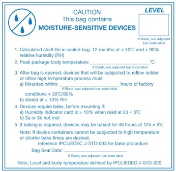
The table below presents the MSL definitions per IPC/JEDEC's standard. Also refer to the “Moisture Sensitivity Caution Label” on the packing material, which contains information about the moisture sensitivity level of Freescale products. Components must be mounted and reflowed within the allowable period of time (floor life out of the bag), and the maximum reflow temperature does not be exceeded during board assembly at the customer’s facility.
|
|
If moisture-sensitive components have been exposed to ambient air for longer than the specified time according to their MSL rating, or if the humidity indicator card indicates too much moisture after opening a Moisture Barrier Bag (MBB), then the components are required to be baked prior to the assembly process. To determine allowable maximum temperature, see the imprints/labels on the respective packing. Below is a table indicating recommended baking times:-
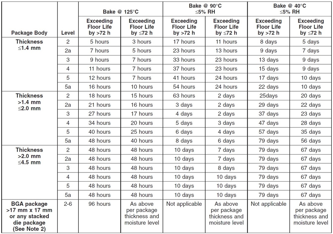
If the components are supplied in tape and reeled, it is possible to bake without removing the components from the packaging but the recommended bake temperature is 40C. If a bake temperature higher than that is used, the cover tape and other elements of the packaging will degrade to the point that it becomes impossible to reliably use an automated tape feeder.
If the recommended bake duration at 40C is unacceptably long, then it is best to remove the components from tape and reel and bake them in bulk at 125C. Bake durations at 125C are significantly shorter as can be seen in the table above. After baking in bulk you can have the components re-packaged into tape and reeled, load to matrix tray, or arrange to have them hand-placed. The most logical choice depends on the specific application, component body size, and quantity of components that you're dealing with.
An Increase in Efficiency and Productivity
It’s a shocking statistic to read that within the electronics industry many surface mount operations, particularly within the sub-contract manufacturing sector, run as low as 20% efficient.
There are many reasons that contribute to this figure but it fundamentally means that only 20% of the capital investment is being utilized. Financially speaking, this will lead to a higher cost of ownership and a slower return on investment. For the customer, it can cause longer lead times for their product and therefore the business will not be as competitive in the market place.
With production efficiencies at this level there will be many knock-on effects that will have an impact on the business such as larger batch sizes, more parts in stock, more assemblies in WIP (work in progress) and slower reaction times to customer change requirements.
With all this in mind there is a strong incentive to improve efficiency while maintaining quality.

We also offer a general consultation service to discuss any particular challenge you may be facing.
If this of interest please send a message using the Contact Page
If this of interest please send a message using the Contact Page
