SURFACE MOUNT PROCESS
  • Home
  • Articles
    • A GUIDE TO EFFECTIVE STENCIL DESIGN
    • SOLDER PASTE PRINTING PROCESS
    • SOLDER PASTE INSPECTION PROCESS
    • COMPONENT PLACEMENT PROCESS
    • REFLOW SOLDERING PROCESS
    • POST-REFLOW AOI PROCESS
    • THROUGH-HOLE ASSEMBLY - SELECTIVE SOLDERING
    • Cleaning 'No-Clean' flux residues and other contaminants
    • Environmental Protection - Conformal Coating
    • Hand soldering and rework of surface mount components to IPC class 3
  • FAQ
    • Solder paste handling
    • Type 3 or Type 4 Solder Paste
    • Cleaning a misprinted PCB
    • Solder Paste Quality Control
    • What factors affect solder paste transfer efficiency
    • What stencil thickness should be used?
    • What is the difference between aspect ratio and area ratio of stencil apertures?
    • What squeegee speed should be used?
    • What squeegee pressure should be used?
    • What the differences between 'on-contact' printing and 'gap' printing?
    • What separation speed to use in solder paste printing?
    • What are the benefits / challenges of using halogen-free solder paste?
    • What is the best stencil aperture shape for solder paste transfer efficiency?
    • PCB delamination during reflow
    • What are the different types of reflow profile?
    • ROSE (Resistivity of Solvent Extract) testing
    • How do you validate a PCBA cleaning process?
    • Why clean a pcba that has been soldered using no-clean flux
    • How do engineered cleaning fluids such as Zestron and Kyzen work
    • How do engineered cleaning fluids affect surface tension and wetting angle?
    • How does the pH level affect engineered cleaning fluids?
    • How do mixed-bed and carbon filters work in PCB cleaning systems?
    • What are the risks of using ultrasonics to clean PCBA's?
    • What are the differences between 'Water-soluble' and 'No-clean' flux?
    • What is the difference between ionic and non-ionic contamination?
    • What causes electrochemical migration (ECM)?
    • What are methods of masking before conformal coating?
    • How to apply conformal coating by brushing?
    • How to apply conformal coating using dipping?
    • How to apply conformal coating using spray/aerosol?
    • How do selective robots apply conformal coating?
    • What is the best method to dry/cure conformal coating?
    • What concerns are there when demasking?
    • What should be checked when inspecting after conformal coating?
    • How to check the adhesion of conformal coating?
    • Tape and Reel Packaging Standards
    • What is 'Package on Package' (POP)?
    • Stock control and component attrition
    • BOM Comparison Software
    • Comparison of SAC305 and SAC387 Lead-Free Solder Alloys
    • What is a 'Eutectic' solder alloy?
    • What does 'SMT' stand for?
    • What does the term voiding mean?
    • How is void percentage calculated?
    • How to reduce voids in QFN device ground connection?
    • Low temperature lead free solder paste
    • CAD EXTRACTION
    • How are PCB's manufactured?
    • What are the IPC standards that govern electronics manufacturing processes?
    • What are the differences between SMEMA and HERMES?
  • Contact
  • Store

TOOLING DESIGN AND MANUFACTURE SERVICE


There are many ways to improve the surface mount process efficiency and assembly quality.  Below are some examples of some custom tooling solutions that are available to be ordered - Please send a message if this of interest or if you have a particular design you would like made.

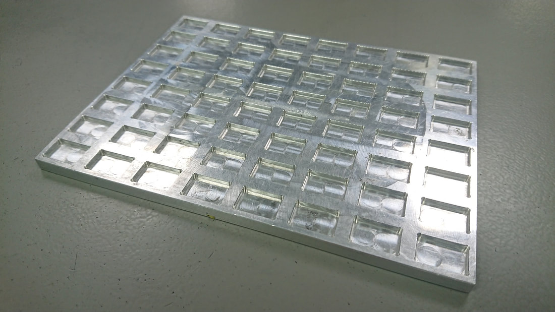
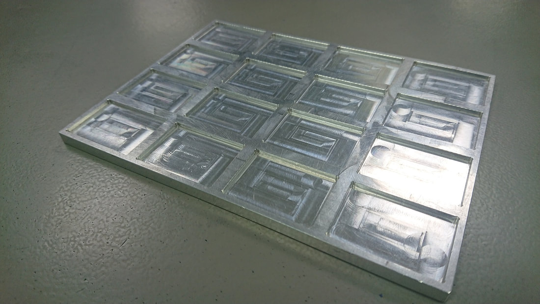
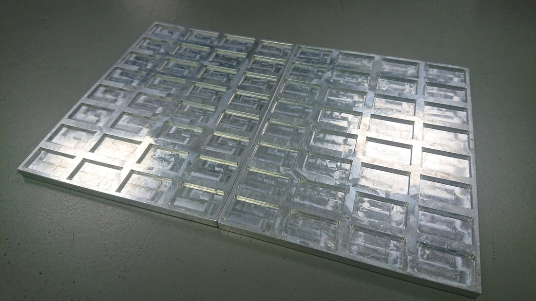
Component feeding trays

These component feeding trays are designed to enable components supplied loose to be loaded to the component placement machine to avoid hand placements.  The trays are double sided so they can have two different sizes of pocket on the same tray and also can be pushed together and taught as one tray to save time - Request quote

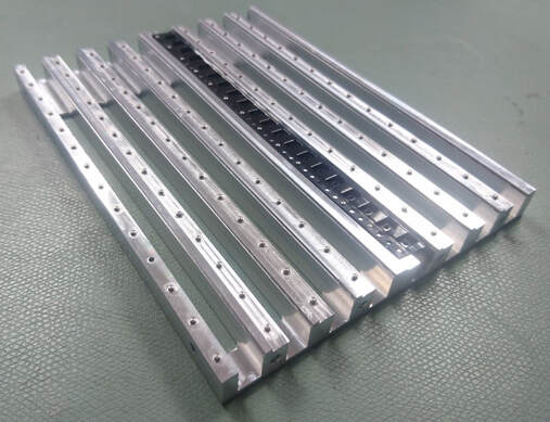
Variable width quick setup PCB support

To enable a consistent solder paste printing and component placement process it is very important to have sufficient PCB support.  For double sided assemblies an adaptable PCB support system is necessary – For single sided assemblies however a simpler, more cost effective solution is available as can be seen below - Request quote
Picture
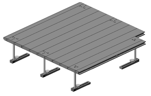
The system above is made up of aluminium support plates that can be quickly connected together for a wide range of PCB widths.  This system is particularly useful for companies such as CEM's that produce high mix – low volumes batches of assemblies that have a high number of change overs.

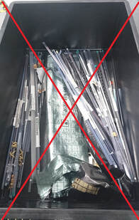
Short tape feeder plate for 12mm and 16mm tape

When building batches of assemblies with low volumes one of the biggest challenges can be how components are supplied.  If only a small quantity of components are ordered then they will either be supplied loose in bags which can be loaded into trays as above or they will be supplied in short strips of tape.  Short strips of tape can be difficult to load onto feeders and so one solution is to use the feeding plates shown below - Request quote
Picture

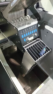
Europlacer belt feeder IC tube holder

When building batches of assemblies that use many different components supplied in tubes one of the causes for machine downtime is looking for the correct tube of parts when a tube runs out.  A solution has been designed for Europlacer belt feeders that holds the tubes of components in a position that can be quickly accessed to reduce the time lost - Request quote
Picture
Picture
Picture

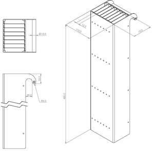
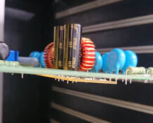
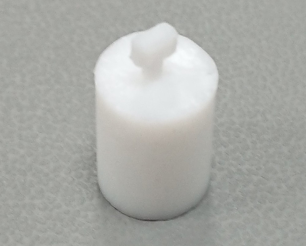
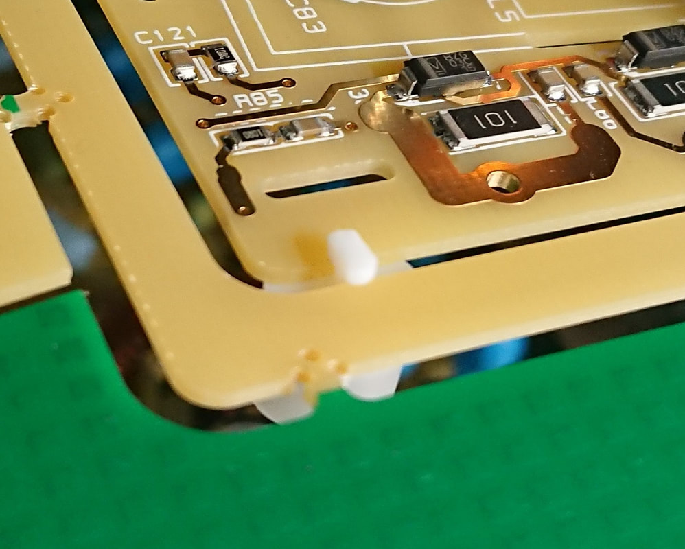
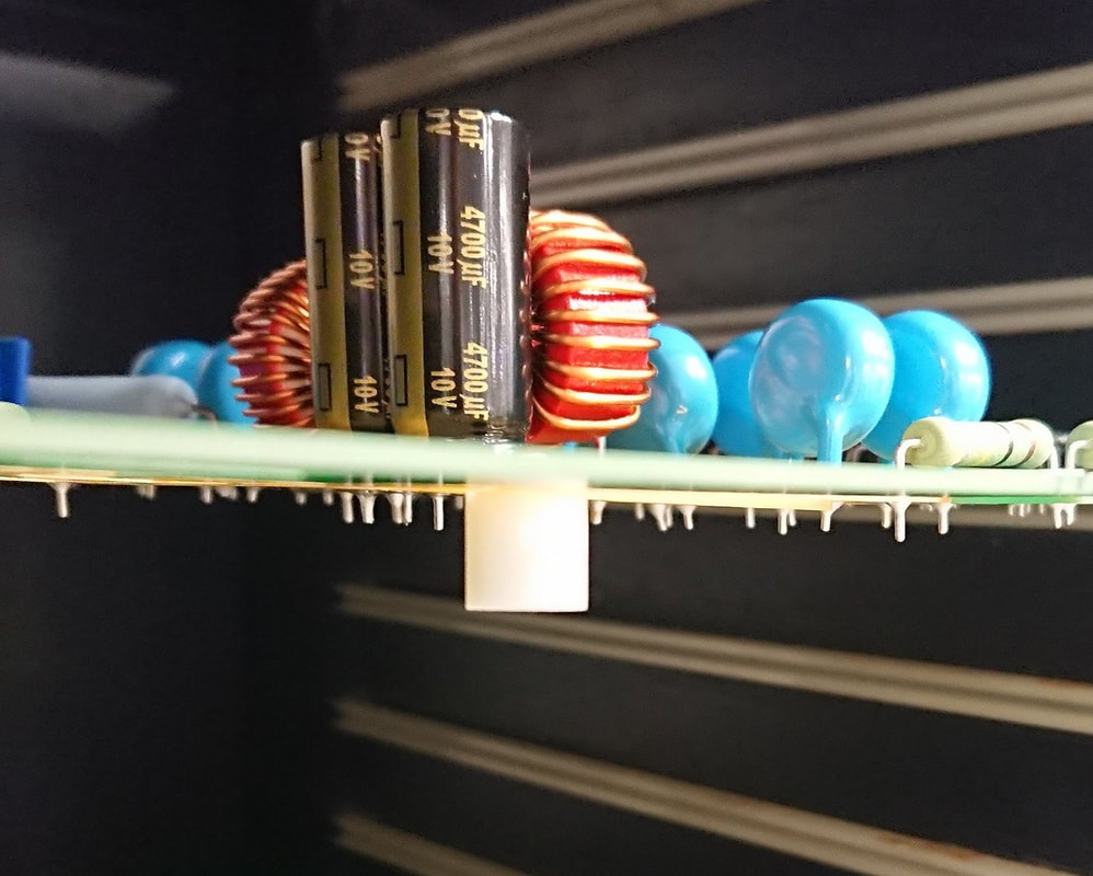
PCB supports for Selective Solder Process

When assemblies are required to be selective soldered it is important that the PCB is flat to obtain consistent results.  Some PCB's, especially if they contain high voltage areas, will have slots machined making the PCB prone to sag - this will be more noticeable when components are fitted.  One solution to hold the PCB flat during the selective soldering process is to fit PCB supports that can be seen below.  The supports can be manufactured according to the width of the slots and they are fitted by simply pushing the support into the slot and twisting 90 degrees to secure.  After the selective soldering process they can easily be removed by twisting 90 degrees and pulling out of the slot - Request quote
Picture
Picture
Picture
Picture

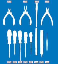
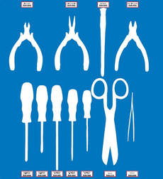
Shadow Boards for 5S

When implementing 5S within any manufacturing area one of the key improvements is the introduction of 'Shadow Boards'.  There are many ways of making these but due the custom nature it can be a challenge to find a company to make them.  Please send a message if you have a requirement.
Picture
Picture

© COPYRIGHT 2015. ALL RIGHTS RESERVED.