SURFACE MOUNT PROCESS
  • Home
  • Articles
    • A GUIDE TO EFFECTIVE STENCIL DESIGN
    • SOLDER PASTE PRINTING PROCESS
    • SOLDER PASTE INSPECTION PROCESS
    • COMPONENT PLACEMENT PROCESS
    • REFLOW SOLDERING PROCESS
    • POST-REFLOW AOI PROCESS
    • THROUGH-HOLE ASSEMBLY - SELECTIVE SOLDERING
    • Cleaning 'No-Clean' flux residues and other contaminants
    • Environmental Protection - Conformal Coating
    • Hand soldering and rework of surface mount components to IPC class 3
  • FAQ
    • Solder paste handling
    • Type 3 or Type 4 Solder Paste
    • Cleaning a misprinted PCB
    • Solder Paste Quality Control
    • What factors affect solder paste transfer efficiency
    • What stencil thickness should be used?
    • What is the difference between aspect ratio and area ratio of stencil apertures?
    • What squeegee speed should be used?
    • What squeegee pressure should be used?
    • What the differences between 'on-contact' printing and 'gap' printing?
    • What separation speed to use in solder paste printing?
    • What are the benefits / challenges of using halogen-free solder paste?
    • What is the best stencil aperture shape for solder paste transfer efficiency?
    • PCB delamination during reflow
    • What are the different types of reflow profile?
    • ROSE (Resistivity of Solvent Extract) testing
    • How do you validate a PCBA cleaning process?
    • Why clean a pcba that has been soldered using no-clean flux
    • How do engineered cleaning fluids such as Zestron and Kyzen work
    • How do engineered cleaning fluids affect surface tension and wetting angle?
    • How does the pH level affect engineered cleaning fluids?
    • How do mixed-bed and carbon filters work in PCB cleaning systems?
    • What are the risks of using ultrasonics to clean PCBA's?
    • What are the differences between 'Water-soluble' and 'No-clean' flux?
    • What is the difference between ionic and non-ionic contamination?
    • What causes electrochemical migration (ECM)?
    • What are methods of masking before conformal coating?
    • How to apply conformal coating by brushing?
    • How to apply conformal coating using dipping?
    • How to apply conformal coating using spray/aerosol?
    • How do selective robots apply conformal coating?
    • What is the best method to dry/cure conformal coating?
    • What concerns are there when demasking?
    • What should be checked when inspecting after conformal coating?
    • How to check the adhesion of conformal coating?
    • Tape and Reel Packaging Standards
    • What is 'Package on Package' (POP)?
    • Stock control and component attrition
    • BOM Comparison Software
    • Comparison of SAC305 and SAC387 Lead-Free Solder Alloys
    • What is a 'Eutectic' solder alloy?
    • What does 'SMT' stand for?
    • What does the term voiding mean?
    • How is void percentage calculated?
    • How to reduce voids in QFN device ground connection?
    • Low temperature lead free solder paste
    • CAD EXTRACTION
    • How are PCB's manufactured?
    • What are the IPC standards that govern electronics manufacturing processes?
    • What are the differences between SMEMA and HERMES?
  • Contact
  • Store

Comparison of SAC305 and SAC387 Lead-Free Solder Alloys

Picture
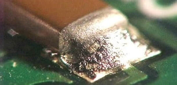
SAC 305 and SAC 387 are both solder alloys commonly used in electronics manufacturing and soldering applications. They belong to the SAC Tin(Sn)-Silver(Ag)-Copper(Cu) family of solder alloys, but they have different compositions and properties. Here's a comparison between SAC 305 and SAC 387:

SAC 305 Lead-Free Solder Alloy

  1. Composition: (The numbers 305 indicate the percentages of silver and copper respectively)
    • Tin (Sn): Approximately 96.5%
    • Silver (Ag): Approximately 3%
    • Copper (Cu): Approximately 0.5%
  2. Melting Point: SAC 305 has a melting point in the range of 217-220°C (422-428°F).
  3. Characteristics:
    • Good wetting properties.
    • Good electrical conductivity.
    • Strong and reliable solder joints compared to low-temperature solder alloys.
    • Good corrosion resistance.
  4. Common Uses: SAC 305 is widely used in surface-mount technology (SMT), through-hole soldering, and reflow soldering processes for various electronic components.

SAC 387 Lead-Free Solder Alloy

  1. Composition: (The numbers 387 indicate the percentages of silver and copper respectively)
    • Tin (Sn): Approximately 95.5%
    • Silver (Ag): Approximately 3.8%
    • Copper (Cu): Approximately 0.7%
  2. Melting Point: SAC 387 has a slightly higher melting point compared to SAC 305, typically around 219-225°C (426-437°F).
  3. Characteristics:
    • Good wetting properties and enhanced solderability due to a higher silver content.
    • Improved Electrical Conductivity due to higher silver content.
    • Strong and reliable solder joints compared to low-temperature solder alloys.
    • Enhanced Corrosion Resistance due to higher silver content.
  4. Common Uses: SAC 387 is used in electronics soldering applications where component solderability is a challenge, corrosion is a possibility and/or low electrical resistance is needed.

The choice between SAC 305 and SAC 387 depends on the specific requirements of the soldering application, including the materials being joined, the soldering process, and the desired properties of the solder joints. Both alloys offer good performance and reliability, although SAC305 is more widely used due to its lower cost and better availability - SAC387 tends to be used in  more challenging applications.
© COPYRIGHT 2015. ALL RIGHTS RESERVED.